Stop the noise, locate the fault.
Wire Journal International
March 2021
Wire and cable
In brief
- Intermittent sparker blows on a tandem line can have one fault or several behind them, and they come and go as the line runs.
- Verify the process conditions first, then check the line from the conductor wipe to the sparker while it is still running.
- If the faults are still there after every check, shut the line down until the fault is located.
5 to 7 min
from the first fault to the end of the running checks, depending on the line
Sparker blows are menacing faults that trigger alarms, buzzers, flashing lights, etc., notifying you that there is a defect in the wire you are producing. Troubleshooting sporadic or intermittent sparker blows can be quite difficult, especially for high-speed insulating lines. This article does not address sparker blows caused from raw materials or processing. Rather, it covers what causes them, with a focus on those annoying mystery faults that seem to come and go by the minutes or hours. A sparker blow may have one or multiple faults, and they may disappear only to return sporadically/intermittently as the line runs.
High-line speeds are normal for a tandem extrusion line where the copper conductor is drawn down to size, annealed and insulated in one continuous process. Most manufacturers use a pressure tip and die setup to produce a conductor with good adhesion and smooth surface. The tandem line comes with additional process equipment, which adds more process variables.
- Wire drawing
- Annealer
- PreheaterConductor clean going in. Preheat temperature verified.
- Conductor wipeNot loaded with copper dust. Paper or cotton only.
- Extruder and crossheadSet points against actuals. Heaters and thermocouples.
- Water troughSurface uniform and smooth.
- Wet capstanNo crossed or double-wrapped wire. Water flowing.
- Air wipeWire dry. No rub point.
- Spark testerNo water or debris in the electrodes.
- Take-up
Method of response
What should a company do when there is a sparker blow warning? Does it mean you are either making scrap or could soon? When do you have to shut the line down?
The key is to know what exactly is happening. Locating the cause of sparker blows can be difficult, and when they are intermittent it’s both that and frustrating to locate the root cause. Most processors will continue to run the line and make several visual checks and/or parameter changes prior to shutting the line down. The thinking is that it is easier to locate certain defects when the line is running, and that shutting down or starting up such lines is problematic due to the increased potential for wire breaks during the shutdown or startup.
- Line runningVerify the processCompare set points with actuals: diameter, temperatures, back pressure, RPMs, motor load and material feed.
- Line still runningCheck along the lineConductor surface, wipe, preheat, the surface after the crosshead, the wet capstan, then the sparker itself.
- Faults still thereShut down and locateFind the fault visually, rewind through a sparker, or use a fault locator or the footage on printed tags.
- 0
- 1
- 2
- 3
- 4
- 5
- 6
- 7
- 8
- 9
- 10
Timing as given in the article. It depends on the length of the extrusion line and its configuration.
Process checks
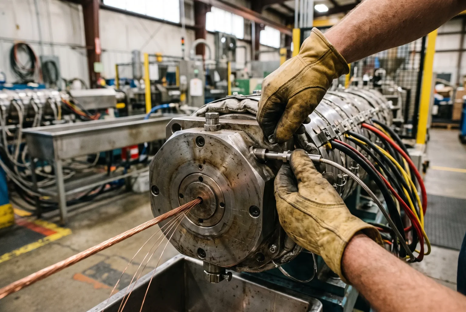
The best place to start is to verify the process conditions. Review the diameter gauge and operation set points and compare them to actual set points and parameters for temperature, back pressure, RPMs and motor load. Verify that there was not an interruption in material feed and pressure. Confirm temperatures for all the auxiliary zones, such as the die, head and flange. Check the heaters and thermocouples both visually and manually.
Make sure that the thermocouples are plugged in properly; that the probe end is in contact against the components being controlled; and that the temperature controller readout changes when handling the thermocouple or adapter plug. I have seen premature burning in the crosshead when the thermocouple was installed with the end of the probe over an inch away from the surface it was measuring. Another common error in the same area is that the thermocouples and power cords could be crossed, resulting in one zone constantly calling for heat as the thermocouple is in a different zone.
Process checks, in short
- Diameter gauge and operation set points against actuals
- Temperature, back pressure, RPMs and motor load
- No interruption in material feed or pressure
- Auxiliary zone temperatures: die, head and flange
- Heaters and thermocouples, visually and by hand
- Thermocouple probe in contact with the part it controls
- Thermocouples and power cords not crossed between zones
The above checklist shouldn’t find such problems, but they can happen, so it is good to first eliminate those possibilities. If the heats and other processing parameters, including diameter, appear stable, then additional checks are required. Below is what I recommend.
Conductor surface before the crosshead
Check the conductor surface prior to entering the crosshead. Is the conductor dry, clean of residue and copper dust? Most manufacturers use a wipe or other method to keep the conductor clean prior to insulating, but these are not foolproof. A line can be running fine but abruptly suffer a flurry of sparker blows due to a conductor wipe being full of copper dust. How? The dust can make its way into the tip and cause a void under the insulation, resulting in the sparker blow alarms.
The wipe, and what it is made of
Keep the surface of the conductor clean as it enters a tandem line preheat as it will burn off most of the remaining oils or water. Usually there is a wipe between the preheater and crosshead. Use a brown paper towel, napkin or other type of wipe made from paper or cotton. Stay away from synthetic materials, as pieces of the wipe can pack the pressure tip, causing sparker blows or wire breaks versus cotton or paper, which will degrade into ashes.
Use
Paper or cotton. A brown paper towel, a napkin or a similar wipe. It degrades into ashes.
Avoid
Synthetic materials. Pieces of the wipe can pack the pressure tip and cause sparker blows or wire breaks.
Preheat temperature
Check the preheat with various gauges or surface heat indicators in strip or stick form. The pre-heat temperature is important for conductors as the next step improves adhesion and helps maintain physical properties, such as tensile strength and elongation of the insulation material.
Surface after the crosshead and down the line
If the conductor surface is normal, the next check is right after the cross head, where the insulation is applied to the conductor. Often, operators will feel the conductor after it is in the water trough to determine if the product is uniform and smooth. This takes experience and is not the safest way, but many experienced operators continue to do it. After the initial surface check, focus on the conductor surface at several different points down the line, especially where there may be a potential rub point that can damage the insulation sheaves or air-wipes. Any guide can be a culprit.
The wet capstan
One prime place to check is the entrance and exit of the wet capstan. The wires can become crossed inside or get double wrapped in a groove, causing excessive pressure on the wire against the side of the sheaves. Another capstan variable is a lack of water due to clogged nozzles. Or, the line may not have been set up to have the cooling water start with the line, resulting in a dry capstan. These are systemic checks along the line where the surface damage can be detected.
Back to the sparker
If no obvious defect is felt on the product, it’s time to return to the sparker. There could be water in the sparker from wet wire due to a faulty air wipe or an accumulation of debris from wire breaks and/or startups. From the start of the faults to this point is approximately five to seven minutes, depending on the length of the extrusion line and its configuration. If the sparker faults are within specification but at maximum allowed, make your last checks while the line is still running.
Examples of sparker blow
Drawings stand in for the three photographs printed with the article in Wire Journal International.
The above photos show three types of problems that at first glance can look similar when detecting and evaluating the sparker blow. You can determine if copper dust (see Photo 1) was the cause by stripping away the insulation of the conductor at the defect to check for a pocket of copper dust. If there is a bubble in the insulation with no impurities underneath, the suspect would be a dirty or wet conductor, or a nylon void caused by burnt carbon. See Photo 2. If after all your checks the faults still exist, the line must be shut down until the fault is located. Depending on the type of put-ups on the take-up end, you could try to find a fault visually, pass the conductor back through a sparker on a rewind machine or utilize other tools the facility may possess. The rework/rewind line operator can rewind to the fault (sparker goes off) as a sample can be used to help determine the location on the insulating line where the damage is occurring. The sparker will leave a burn mark if the wire has spent too much residence time in the electrodes of the sparkers, making it difficult to determine the cause. See Photo 3.
Fault locators are offered that can be hooked up to the ends of the conductor to locate the footage from the top or bottom of the put up to where the fault is located. The newer insulating lines can be equipped with digitally printed tags that list product information, footage, date, shift proceed and the number of faults with the length location of the faults printed on the tag. This, in turn, can be used to locate the fault while passing through other downstream operations, versus adding the process of rework.
All the above measures can help you find the fault to understand the root cause of a sparker blow. This article cannot list every cause of pinholes and sparker blows, but the goal is to supply personnel with more of a scope and explanation of the variables on line that can be a root cause for sporadic, intermittent sparker blows.
First published as “Extrusion woes 101: sparker blows” in Wire Journal International, March 2021, in The Fundamentals section.