
Florida-based. On site at your plant or in an R&D lab.
Markets
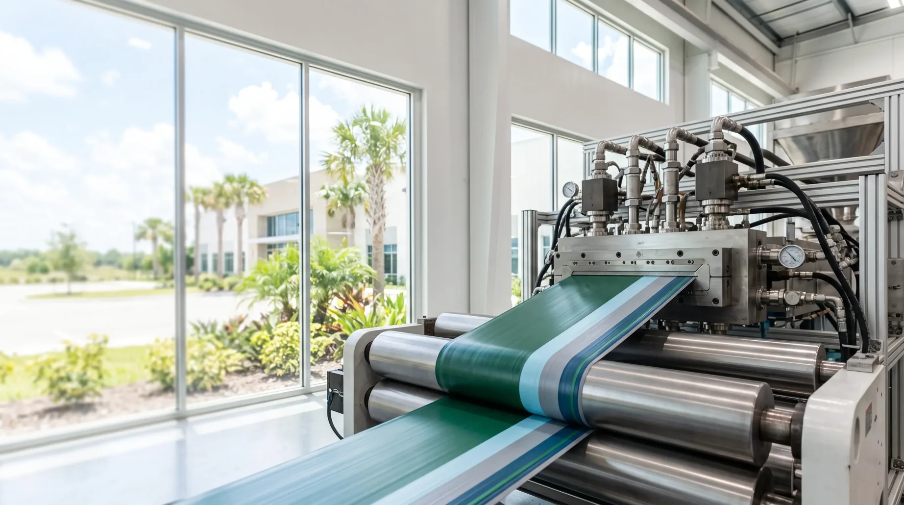
Two to five layers in a single pass. Co-extrusion removes process steps and makes products one material cannot, provided every melt stream arrives at the right temperature, viscosity and rate.
5 layers
in multilayer set-ups GBET has run
1 pass
for products that once needed several processes
3 miles
reel length on a recent single-pass multilayer project
2.1 in.
finished diameter of that construction, over a 0.750 in. core
When melt streams meet, the lower-viscosity material tends to move toward the high-shear region at the wall and can start to wrap around its neighbour. Where the streams join, differences in velocity and stress across the interface can make it wavy. And a small difference in melt temperature between streams is enough to move a layer.
Most multilayer problems come back to those three things, plus the tooling that brings the streams together.
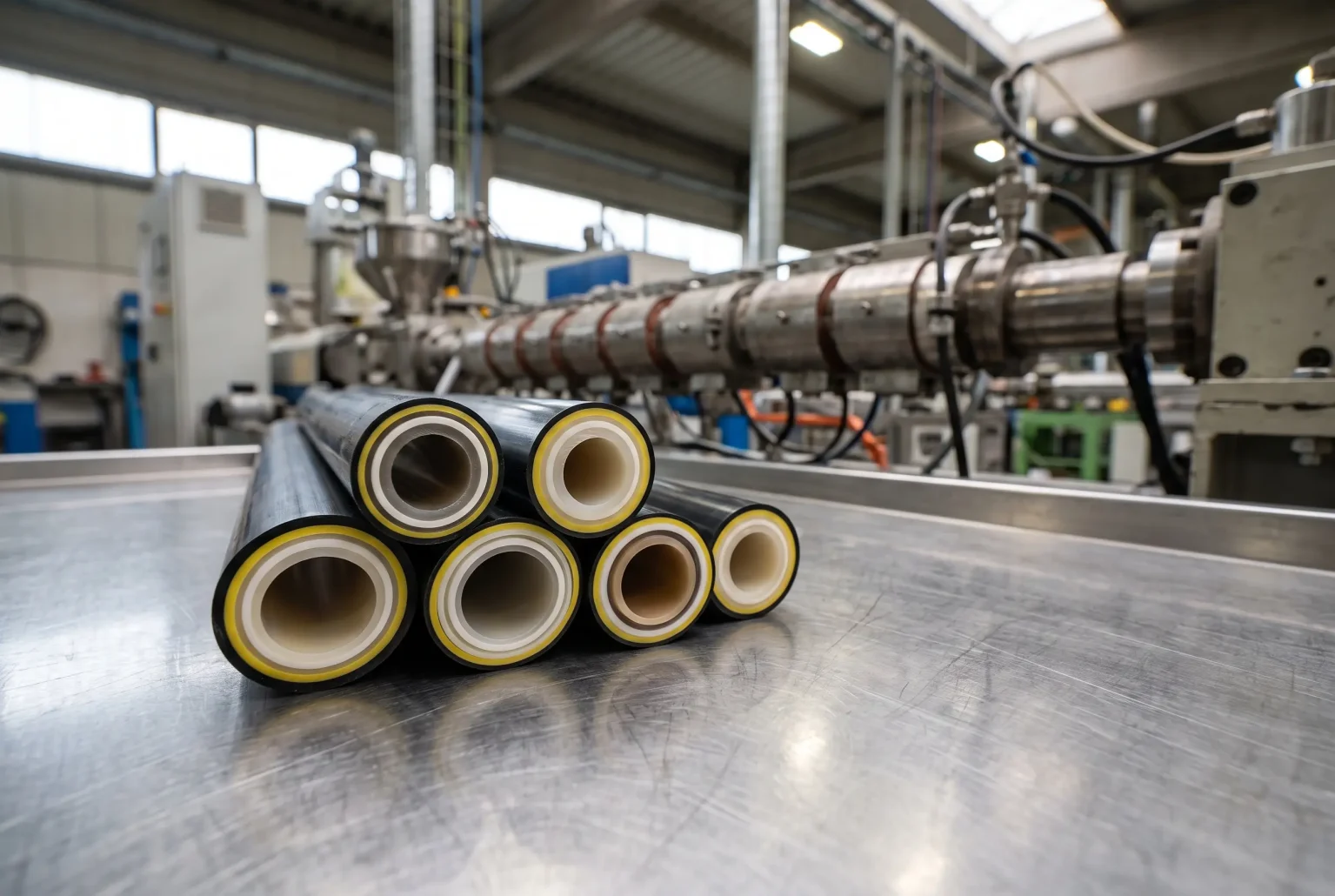
Co-extrusion faults are usually about the relationship between materials, not one material on its own.
| Symptom | Common causes | Where to look first |
|---|---|---|
| Uneven layer thickness | Viscosity mismatch, melt temperature differences between streams, unbalanced flow in the head | Melt temperature of each extruder, head design, output ratios |
| Wavy or rough interface | Instability where the streams merge, driven by stress and velocity differences between layers | Layer ratios, melt temperatures, the geometry where the streams join |
| One layer wrapping around another | Lower-viscosity melt migrating toward the high-shear wall | Material selection, temperature changes that bring the viscosities closer |
| Delamination | Polymers that do not bond and have no tie layer, contamination, low temperature at the join | Tie layer choice, drying, head temperatures |
| Weld or knit lines | Flow that splits around supports in the head and does not fully rejoin | Head design, residence time, melt temperature |
| Start-up scrap | Layers brought on in the wrong order or at the wrong rates, inconsistent purge practice | A written start-up sequence that every shift follows |
Hands-on training on co-extrusion and multilayer set-ups, including start-up sequence and what to change first when a layer moves.
Head and die design reviewed with flow simulation, so that streams are balanced where they join.
Trials to find combinations that run together, and the tie layers they need.
New multilayer constructions taken from prototype to a process that runs in production.
The head design follows from the product. These are the broad choices.
| Design | How it works | Often used for |
|---|---|---|
| Crosshead | The melt turns, usually through 90 degrees, and flows around a core tube, so a wire, core or substrate can pass straight through the head | Wire and cable, sheathing, tubing over a substrate |
| In-line | The melt flows straight through the head around a supported mandrel | Tubing and pipe where nothing has to pass through the centre |
| Spiral designs | Melt is distributed through spiral channels, which avoids the weld lines that support legs leave | Products where weld lines are unacceptable |
| Multilayer heads | Both crosshead and in-line heads are built for several layers, including five-layer configurations | Barrier tubing and multilayer cable constructions |
Straight answers to the questions that come up most in this market.
The usual causes are a viscosity mismatch between the materials, a difference in melt temperature between streams, or flow that is not balanced in the head. Check the actual melt temperature of each extruder first. Barrel setpoints do not tell you what the melt is doing.
When two materials that do not bond have to stay together. A thin layer that adheres to both is extruded between them.
If a wire, core or substrate has to pass through the head, a crosshead. For tubing with nothing through the centre, either can work and the choice depends on the materials, the layer structure and how weld lines are handled. Both are built in multilayer versions.
It shows whether each layer leaves the tooling at a balanced velocity, using the real flow behaviour of each polymer, and where material may hang up. It lets tooling be corrected before it is built.
Up to five, along with single and tandem set-ups.
Track start-up and changeover scrap separately from running scrap so that you can see it. Then standardise the sequence: the order in which extruders are brought on, the rates and the purge. When a start-up works, write it down and have every shift use it.
Tell us what the line is doing, what it should be doing, and what cannot change. You will get a plain answer on whether training, tooling, equipment or process work is the right place to start.
We use cookies to improve your experience on our site. By using our site, you consent to cookies.
Manage your cookie preferences below:
Essential cookies enable basic functions and are necessary for the proper function of the website.
You can find more information in our Cookie Policy.