
Florida-based. On site at your plant or in an R&D lab.
Die design and process engineering
Die design and development, flow analysis, die design improvements, troubleshooting and product development for wire and cable, tubing, profiles and multilayer products.
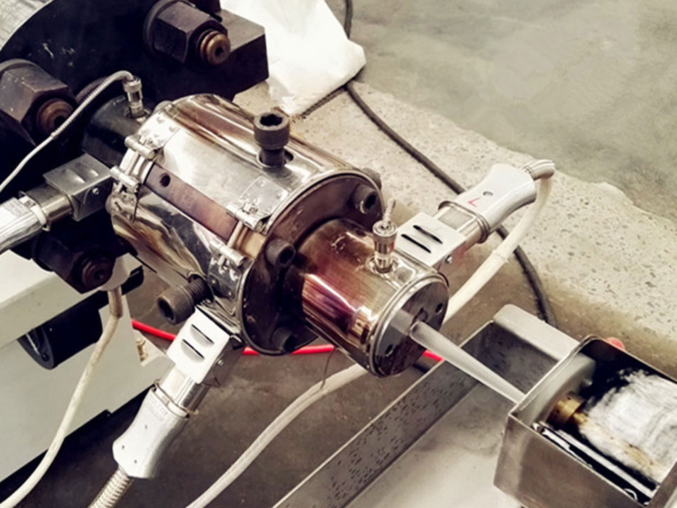
Whether the issue involves equipment, tooling, materials or process conditions, the objective is the same: understand the entire system, find the root cause and develop a practical solution.
New tooling for a new product, from first concept through trials to a die that runs in production.
Simulation of how the melt moves through the tooling, used to balance flow and find problems before steel is cut.
Changes to existing tooling: land lengths, die gaps, tip and die geometry, flow balance.
Multiple-plate profile dies and dry sizing calibration plates for profiles that have to hold their shape.
Co-extrusion with up to five layers, tandem lines and the sheathing of substrates.
Prototype runs and the work of finding the combination of materials, tooling and settings that can be industrialised.
Two short videos from GBET projects.
Melt flow through extrusion tooling, modelled to check balance and residence before a design is released.
A profile die modelled in three dimensions, plate by plate.
1
The product, the materials and the problem, with operating parameters, data sheets and existing tooling drawings on the table.
2
Flow analysis and a review of tip, die and land geometry, draw-down ratio and draw balance for the material.
3
Hands-on trials at the extruder, adjusting tooling and process conditions on real product.
4
A tool set and a set of conditions that run, handed over to the operators who will use them.
The same engineering questions come up in different forms in each market.
| Sector | Typical products | Tooling questions | Process focus |
|---|---|---|---|
| Wire and cable | Insulated conductors, jacketed and multi-conductor cable, fluoropolymer-jacketed constructions | Pressure or tubing tooling, tip and die sizing, concentricity | Preheat, cooling gradient, line speed, spark faults |
| Medical tubing | Single-lumen, multi-lumen and micro-extruded tubing | Draw-down ratio, draw balance, lumen air control | Dimensional stability, cooling, gauging |
| Automotive and industrial tubing | Mono-wall and multilayer tubing, sheathed hose and substrates | Layer distribution, crosshead design for sheathing | Sizing, cooling, adhesion between layers |
| Profiles and conduit | Co-extruded PVC profiles such as wire tray, conduit | Multiple-plate dies, flow balance across the section | Dry sizing calibration, shape retention |
| Co-extrusion and multilayer | Two to five layer tubing, cable and coatings | Where the melt streams join, layer uniformity | Viscosity matching, melt temperature of each stream |
Tooling
Design and build of a multiple-plate profile die with dry sizing calibration plates, for a co-extruded PVC electrical wire tray.
Troubleshooting
On a new line the material would not convey. Land lengths, draw-down ratio and die gap were restricting the feed. The tool set was modified and the customer was up and running.
Product development
The kind of prototype GBET is asked for: a 0.004 in. special alloy conductor with a 0.005 in. fluoropolymer wall.
Product development
A 0.750 in. core with several thermoplastic layers and a fluoropolymer jacket, 2.1 in. finished diameter, on reels three miles long.
It shows how the melt will move through the head and die: whether flow is balanced at the exit, where material may hang up and degrade, and where streams rejoin. Problems found at that stage are fixed on screen, not in steel.
Often, yes. Die design improvements are a regular part of the work. Changes to land length, die gap or tip and die geometry can turn a tool that barely runs into one that runs well.
With pressure tooling the melt meets the wire or core inside the die, under pressure, which gives intimate contact. With tubing tooling a tube of melt is drawn down onto the core outside the die, often with vacuum. The right choice depends on the product, the material and the line speed.
Draw-down ratio compares the cross-section of the melt as it leaves the tooling with the cross-section of the finished product. Draw balance compares the proportions of the die and tip with those of the product, and is usually kept at or slightly above one. Both are chosen for the material.
Yes. Recent work includes a multiple-plate profile die with dry sizing calibration plates for a co-extruded PVC profile.
Drawings and specifications are treated as confidential, and GBET will work under your non-disclosure agreement.
Tell us what the line is doing, what it should be doing, and what cannot change. You will get a plain answer on whether training, tooling, equipment or process work is the right place to start.
We use cookies to improve your experience on our site. By using our site, you consent to cookies.
Manage your cookie preferences below:
Essential cookies enable basic functions and are necessary for the proper function of the website.
You can find more information in our Cookie Policy.